

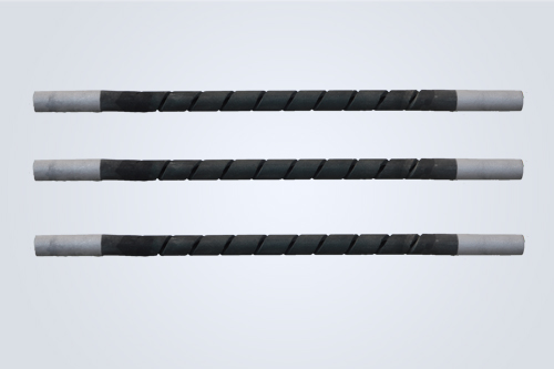
A SiC heater performs best when its geometry matches the furnace chamber instead of being treated as a replaceable rod placed wherever space is available. Hot-zone length, cold-end position, element spacing, wall clearance, electrical resistance, and the location of the workload all shape temperature uniformity. For ceramic, glass, and powder metallurgy furnaces, layout is a thermal design decision as much as an installation detail.
A silicon carbide heater radiates heat from the hot zone into the chamber. If the hot zone is too short, too far from the load, or concentrated in one area, the furnace may show cold corners, uneven firing, or excessive heat near the wall. If the element is too long or poorly supported, the furnace structure and cold ends may be exposed to unnecessary heat.
The layout also affects electrical balance. Silicon carbide resistance changes with temperature and increases gradually with aging, so the circuit and element grouping should leave enough control range to maintain useful power as the rods mature.
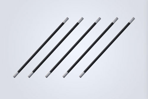
ED rod and DB dumbbell types both serve SiC furnace applications. A straight ED element can suit a long chamber where the heating zone needs to extend across a defined span. A DB form provides a different end and hot-zone arrangement, which can be useful when the furnace structure requires a compact connection pattern.
U and W forms place more heated length within a compact footprint and can help when a furnace needs heat from a sidewall or roof position. W type is associated with three-phase arrangements, while SC and SCR spiral forms offer alternative geometry for smaller or more concentrated heating zones. UX slot elements may be chosen when the furnace structure calls for a slotted profile rather than a simple round rod.
The right question is not which shape looks most powerful. It is whether the active hot zone follows the chamber dimensions, whether the cold ends stay outside the hottest area, and whether the element can be supported without mechanical stress.
The hot zone should face the workload with enough clearance for radiation to spread through the chamber. The cold end must remain cool enough for the connection and furnace wall to operate safely. When the cold end projects too far into the chamber, it can become an unintended heat source; when it stays too far away, usable heating length may be lost.
For a long ceramic kiln, several rows of elements may be distributed along the sidewalls or roof to follow the product path. A glass or metallurgy furnace may need a different arrangement because the charge, viewing openings, and refractory structure alter the heat flow. Placement should be checked against the real load shape rather than only the empty furnace dimensions.
Spacing influences both temperature uniformity and surface load. Elements placed too close together can create local hot regions and make maintenance difficult, while elements placed too far apart may leave cold bands between radiation fields. The element-to-wall distance also matters because the refractory wall can absorb or reflect heat differently from the process load.
A practical layout keeps the distance between the element, heated object, and furnace wall at least three times the element diameter, with center spacing between rods no less than four times the diameter. These values should be treated as design guidance to review alongside furnace size, insulation, element temperature, and the actual charge.
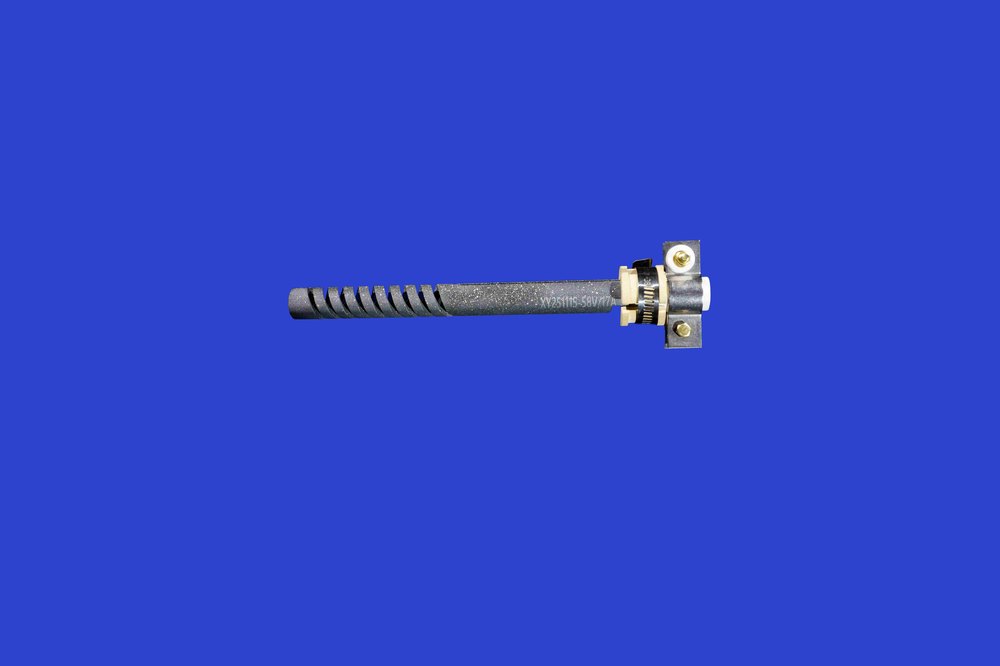
Ceramic firing often needs broad, even radiation over shelves, setters, or a moving kiln path. The layout should account for the height of the ware, airflow during drying, binder release, and the risk that glaze or alkaline vapors may reach the hot zone. A distributed U, W, or ED arrangement may be more useful than a concentrated group at one end of the chamber.
Glass and metallurgy processes can expose elements to vapors, dust, or molten material, so placement should create a practical separation between the hot zone and the charge. Sidewall, roof, or protected-tube arrangements may be considered according to the furnace structure and atmosphere. The element should provide radiant heat without becoming the first surface contacted by corrosive process material.
Powder metallurgy furnaces often require controlled temperature ramps and a stable atmosphere. The heating layout should leave space for fixtures, baskets, or boats while keeping the active zone aligned with the product. Resistance matching and balanced circuit grouping are especially important when several rods share the same heating section.
Songshan provides ED, DB, U, W, SC, SCR, and UX SiC heating element forms, with dimensions described through outer diameter, hot-zone length, cold-end length, overall length, shank spacing, bridge dimensions, and resistance. This format gives furnace engineers a clear way to relate the element to the chamber and power supply.
Songshan SiC heating elements can be matched to chamber geometry and application details.
During a practical design review, Songshan can be considered alongside furnace length, width, and height, workload dimensions, heating rate, target temperature, atmosphere, insulation, voltage, wiring method, and maintenance access. The result should be a layout that distributes heat evenly while keeping connections, refractory openings, and replacement work manageable.
A reliable SiC heater layout begins with the furnace rather than the catalogue shape. Matching hot-zone length, cold-end position, spacing, wall clearance, resistance, and circuit grouping to the real process helps ceramic, glass, and powder metallurgy furnaces achieve more even radiant heating. Songshan SiC heating elements provide several geometries for building that match around the chamber.
For help relating SiC element geometry to a furnace chamber and heating cycle, connect with Songshan's SiC heating element range.
A: Position the active hot zone so it faces the workload and supports even radiation across the chamber. Keep the cold ends and electrical connections outside the hottest region, maintain suitable wall and load clearance, and avoid mechanical pressure on the element. The final position depends on furnace geometry, atmosphere, and heating cycle.
A: They can be useful when a compact connection arrangement needs to provide a longer heated path across a chamber. U and W forms should still be matched to the furnace width, height, power supply, and required temperature distribution. W type may also be considered where a three-phase arrangement is part of the furnace design.
A: Spacing affects radiation overlap, local surface temperature, temperature uniformity, and maintenance access. Rods placed too close may create hot regions, while excessive spacing can leave cold bands. Clearance should be reviewed in relation to element diameter, furnace walls, the heated object, insulation, and the total load.
A: Resistance matching helps distribute electrical load more evenly among grouped elements. Because SiC resistance changes with temperature and increases with aging, large differences between rods can produce uneven heating or accelerate the aging of individual elements. Circuit design should therefore consider initial resistance, wiring method, and future control range.
© Henan Zhengzhou Songshan Enterprise Group Co., Ltd