

2026-11-05
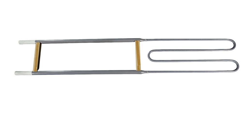
When installing a MoSi2 heating element, five things need to be under control: mechanical stress; support position; cold-end clearance; electrical connection; and start temperature. It is brittle at room temperature and can break from an impact, being forcibly aligned, or connecting to a part that is not flexible enough. An installation free from error results in the hot zone being contained to where it is supposed to be, and enables both elements as well as the furnace structure to respond freely. Songshan MoSi2 elements should be mounted based on the approved drawings rather than visually.
Storage and Installation: MoSi2 heating elements act like a ceramic component. An impact at the hot end, a hard contact with refractory brick, or forceful alignment of a terminal can create an invisible crack. Use supports along the length of a longer element before it is installed and protect against collision.
The material gets more plastic at high temperature, but it cannot be bent or adjusted once the element is in operation. The installation drawing mainly determines the shape, orientation, and connection path. Do not use mechanical force to make up for an incorrect opening position or support.
The furnace wall, insulation, and heated material should remain free of the active hot zone. Local contact can create hot spots, prevent thermal movement, or damage the lining. The support system shall hold the element in a stationary position due to inappropriate load being transferred at the hot/cold section transition.
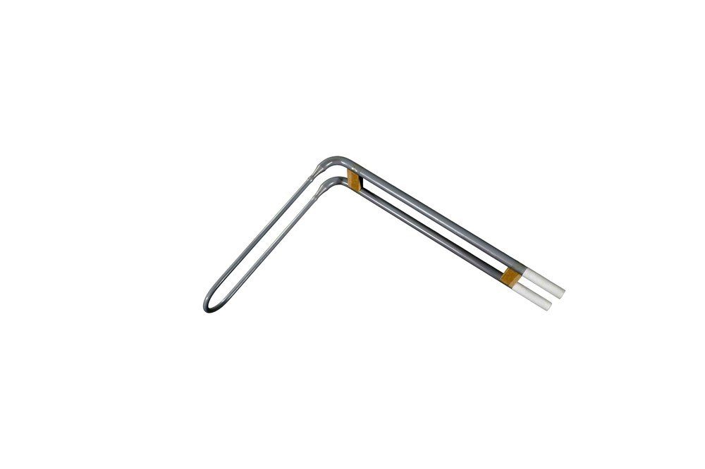
Songshan offers MoSi2 elements in U-, W-, straight-, X-, L-, round-, ring-, spiral-, and M-shaped configurations. Normally, a U-shaped element would be installed with the bend downward, and those cold ends being held up from the top of your furnace. Multi-bend shapes like W distribute heat over a greater area, while bent L-shapes might be used to cover a narrow aperture or corner pathway.
The shape must be the same as the chamber and how you have entered it. Indicate the opening, support locations, hot-zone centerline, cold-end direction, shank spacing, and terminal clearance on a drawing before fabrication or replacement. Even with a product photo, the shape may be right but wrong for an actual furnace.
Both electrical connection and thermal protection are influenced by the cold-end length position. Too deep of a cold end into the hot chamber and it can be too hot at that connection point. But if it is still sitting too far out, then the active zone will not be able to cover this needed area of the furnace. Verify the element holder and furnace-wall opening before installation.
Dimension marks typically comprise diameter, hot-zone length, cold-end length, and shank spacing. Take those values from the drawing and then also test them with the furnace opening before installation. This is crucial for replacement work since insulation/supports/wall openings may have been altered since the original element was installed.
MoSi2 accessories in the form of element holders and aluminum braid connecting straps. The holder supports the piece itself and locks it in place, whilst the strap transfers current without giving a rigid force onto its ceramic-like body. The connection should be made in such a manner as to allow for thermal expansion, without being subject to forcing the element sideways. The connection should be designed to allow thermal expansion without laterally pulling the element.
Keep the area inside the clamp & strap away from high radiant heat. The connection needs to be sufficiently firm for good electrical contact, but not so tight as to induce stress at room temperature. Inspect the terminal, strap and holder and wall opening all as one assembly before closing up on furnace. Inspect the terminal, strap holder, and wall opening as a unit before you close in any furnace.
When a replacement element has varying diameter, cold-end length, or shank spacing, be cautious in assuming the old accessory arrangement is reusable. Dimensional differences of a few mm can shift the hot zone, change terminal temperature, or reposition the circuit. Check the new drawing and furnace hardware in advance of installation.
You would cure a new furnace or one that's been sitting for an extended period prior to it being put in normal service. Water vapor released from moisture in the lining can cause steam or thermal shock and an unstable first firing. Keep the furnace door and ventilation in the positions specified by the manufacturer while raising the temperature gradually through the prescribed drying stages.
MoSi2 is prone to low-temperature oxidation and powdering; therefore, long dwell in the range 400–700°C should be treated with caution. The startup schedule should gradually sweep through this range and not linger in one place or another unnecessarily. The process should closely follow that of the furnace design and element specification.
When full voltage is applied to a cold furnace, the movement of current through it creates an over-current impulse that shortens element, power equipment, and lining life. Staged voltage increase on startup, with temperature ranges adjusted for furnace size and power, is suggested in the technical material. During the first cycle, the operator should observe voltage, current rise, and any abnormal hot spots.
After normal operation (once your furnace reaches this point), document Element position, replacement date and temp/atmosphere and notes. This history, if a failure does later occur, helps tell mechanical damage from excess loading or connection problems and atmospheric effects and even an incorrect start-up procedure. This history can be instrumental in distinguishing mechanical failure from excessive load, connection problems, atmospheric effects, or an unsuitable startup procedure if a later failure does occur.
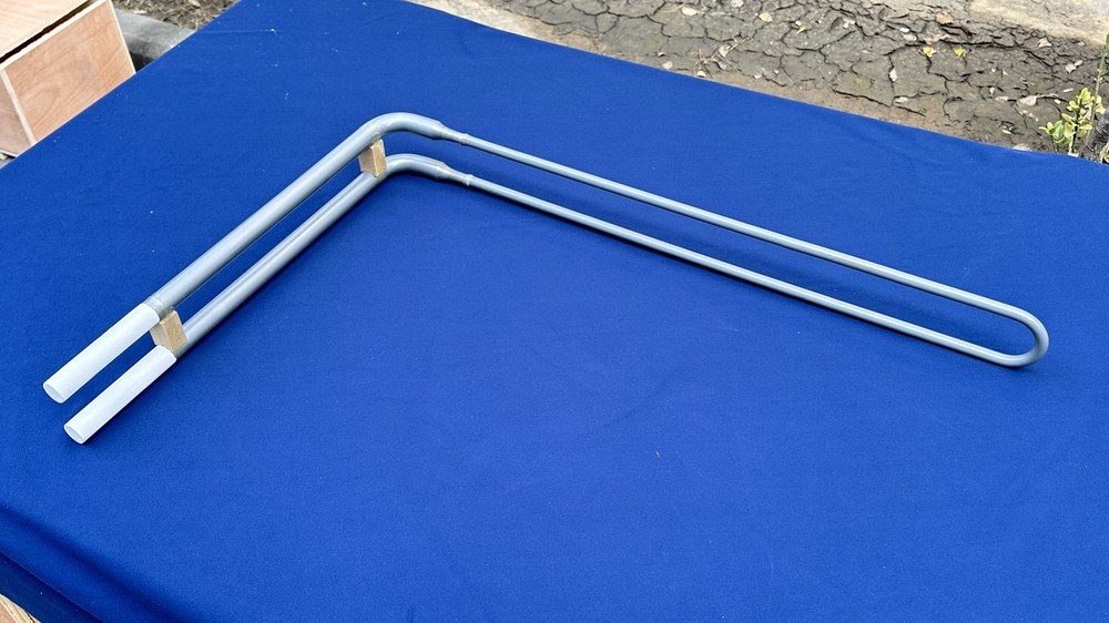
MoSi2 accessories, such as holders and connecting straps, must be verified with the associated element drawing. A replacement request for upcoming projects should have, at the very least: furnace drawing (type), element dimensions and grade resistance of each heating zone plus support arrangement, cold-end position, atmosphere to produce & temperature profile sketch including photographs in current connection area.
When ordering a new furnace, buy with confidence that element orientation will be positioned correctly before wall opening and electrical connections are made; However, if it is an existing furnace, the supports and insulation should be checked prior to any installation of a replacement. This retains the element specification as condition-based rather than a mere dimensional exchange of like for like.
A reliable MoSi2 heating element installation protects not only the heating elements themselves but also their electrical connections and the furnace lining. Proper hot-zone positioning, secure connections, and carefully sequenced drying and startup procedures help minimize the risk of damage and ensure long-term performance.
Contact Songshan Technical Support today for a professional installation review based on your furnace drawings.
A: No. The element shape is catered and produced for the furnace arrangement before incorporation.
A: Vertical hanging helps the holder to hold onto the element and holds the U-bend in the desired location of the furnace. When the furnace is designed for the arrangement, this can reduce unwanted mechanical loading on the hot section.
A: The connecting strap is a conductor that carries current from the bus to the element, but it can flex more than something rigid and non-moving.
© Henan Zhengzhou Songshan Enterprise Group Co., Ltd